Up W7BRI 1430 Power Pack Prev Next Slideshow

 Previous image  Next image  Index page
Top
Hanging #1
Hanging #2
Hanging #3
Attack Goats!
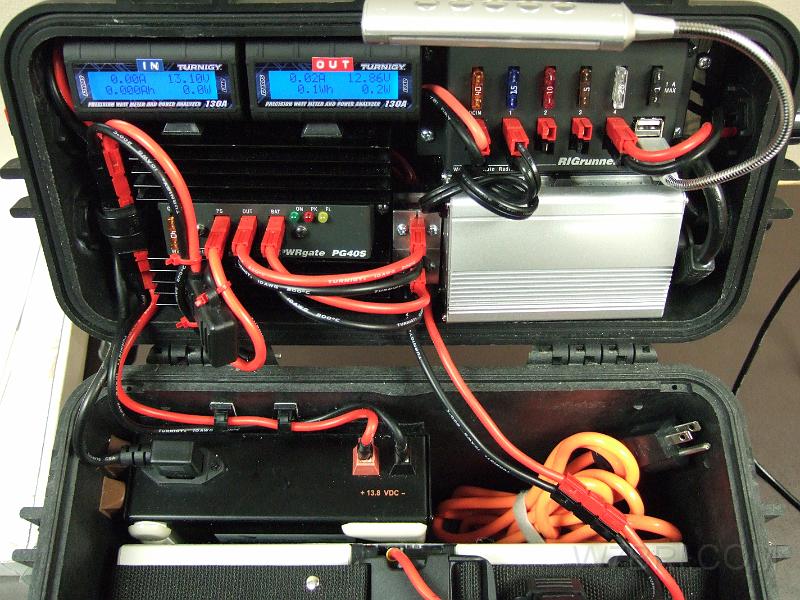
  Top & bottom close up - V2.jpg - To the casual eye, not much has changed from the original design.  It uses the same PWRgate, inverter and power supply (wires visible at the bottom of the image) and batteries (not shown; Hawker Odyssey PC680s as an option).  The Red-Dee PS-4 PowerPole splitter has been re-modified with sturdier "meltable wall" shrink tube and secured with a plastic clamp.  The PVC-coated power cables have all been replaced with superior 200C/400F silicone-coated cable.  I decided to swap out the RIGrunner 4005 for the 4004U version.  Although it has one less PowerPole jack, I actually gained a free PP jack because I ditched the thermometer (which required a 12V -> 5V adapter) and the LED strip (needed a PP jack).  I now use a much brighter flexible    USB LED light   . In the middle of the lid (between the PWRgate and silver inverter), I added a PowerPole pedestal that connects the PWRgate to wires behind the back plate that run to the new backlit Turnigy meters.  One of the meters connects to the battery via the two holes at the bottom of the pedestal (cords are hanging down).  Why did I install two meters?  Well, I discovered that the reasonably-priced meters that would fit in my case all had the same limitation: Although they will pass current, etc. from the load to the source (right to left) side of the meter, they will NOT display it. Anyhow, this "flaw" is a problem when you have a bidirectional power system and need to simultaneously view the charge (in) and discharge (out).  Sure, you could swap cables with one meter like an old-timey switch board operator (and lose all of your stored data in the process), but I wanted to make something better that didn't require guesswork or an instruction book.  As for how I wired the meters, it's difficult to explain, but here goes (see the cheesy MS Paint diagram, below):  Let's call the incoming meter "IN" and the outgoing meter "OUT".  Both have "source" and "load" cables; "IN/S", "IN/L", "OUT/S" and "OUT/L".  The PWRgate charger has "PS", "OUT" and "BAT" jacks; "PG/PS", "PG/OUT", "PG/BAT".  The jacks on the PowerPole pedestal between the PWRgate and inverter that PG/OUT and PG/BAT connects to are called "PP/OUT/FRONT", "PP/OUT/BACK", "PP/BAT/FRONT" and "PP/BAT/BACK".  Here's how they connect: AC/DC in -> PS4 splitter -> PG/PS -> PG/OUT and PG/BAT; PG/OUT -> PP/OUT/FRONT -> PP/OUT/BACK -> OUT/S -> OUT/L -> RIGrunner (RR)-> load/DC OUT. PG/BAT -> PP/BAT/FRONT -> PP/BAT/BACK -> IN/S -> IN/L -> BATTERY.  When no external AC/DC is present, the battery takes over: BATTERY -> IN/L -> IN/S -> PP/BAT/BACK -> PP/BAT/FRONT -> PG/BAT -> PG/OUT -> PP/OUT/FRONT -> PP/OUT/BACK -> OUT/S -> OUT/L -> RR -> DC OUT.  That's about a dozen steps, but it all seems to flow efficiently.  I think Rube Goldberg would've liked it.  :-)  
3Q profile - V2 #1
3Q profile - V2 #2
AC & DC inputs - V2
Output side with AC & DC cables - V2
1430PP - V2 diagram

Top & bottom close up - V2
Camera: FUJIFILM FinePix F10 | Date: 5/9/11 8:30 PM | Resolution: 2848 x 2136
Total images: 19 | Last update: 5/10/11 11:59 PM | Help